Inexpensive 1 Watt Node
I have been able to put together inexpensive headless nodes capable of approximately 1 Watt output. I will share what I did so you can make your own.
I started out with Heltec boards only capable of approximately 150mW output.These are fine in high or open areas with a far line of sight or operation in node dense areas, but I am usually a distance of several miles from the next node. I bought a couple of Station G2s which will be set up as infrastructure nodes (or already are depending on when you're reading this) and I have been impressed with the improvement in reliability. These units have quite a few components and are not inexpensive. A good compromise for most other places would be to get more nodes capable of nearing the 30dBm power limit, but using as few components as possible to keep costs low. This may be a good option for a rooftop node build. This build is compatible with the "supported" DIY V1 firmware available on the Meshtastic Flasher.
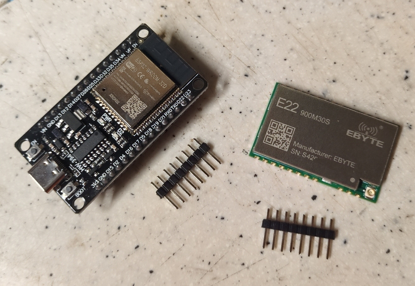
WARNING This does not work with the DIY V1 binary on Meshtastic Flasher using the ESP32-S3 Dev boards. Make sure you use ESP32-WROOM-32 boards with the pinout the same as shown in my picture. I am still working on getting something readily flashable hooked to the ESP32-S3 Dev boards.

Parts Needed
ESP32 Board - I believe pretty much any ESP32 prototyping board works for standard functionality right now as long as you have access to all the necessary pins, but some models are better than others. I used ones with 40 pins on the GPIO connectors. I believe there are boards out there with 30 pins, and I am not sure if they provide all the needed connections. There are several models with varying speed and amounts of storage and RAM. The first one of these I have built as a proof of concept was built with an ESP32-WROOM-32 I had laying around. I believe it is only 2MB RAM, which means already it is limited, as it will not support Store and Forward operation with Meshtastic. If you don't already have a board laying around, I would recommend ESP32-S3 N16R8 - this is 16MB NVRAM storage and 8MB RAM. I believe this is the same MCU that the Station G2 uses.
This one would have enough power and storage to install the web interface if you would like it and also be able to do more advanced things like store and forward. Some of the lesser MCUs get slow when doing things like MQTT and telemetry.
Ebyte E22 900M30S - This is a LoRA module with an SX1262 radio with amplified output capable of approximately 30dBm. These are hard to find on Amazon, but I was able to order from there. They appeared to come directly from the manufacturer in China and took a couple weeks. Can be had on AliExpress for less than $10 at the time of this writing.
IPEX-1 to SMA Jumper This is so you can attach some sort of real antenna. If you want to directly connect a fiberglass stick antenna, you may instead want a jumper that is IPEX-1 to N Female connector.
Jumper Wiring I had Dupont Female to Female ribbon jumper cables in my parts bin along with pin headers to add to the Ebyte Module. My ESP32 boards already had pin headers soldered to the board.
Build Process
Soldering There's not much soldering to do. All I did was solder pin headers to the necessary pins on the Ebyte E22 module. I did an absolutely terrible job at this, but it was good enough to work. Be careful to not accidentally solder the pins to the metal shield on top of the module. I need some new soldering gear as my tips are all worn, and I was in a rush to get this proof of concept working so I had my iron on way too hot. You only need to solder one ground and one VCC, as the grounds are all tied together. I haven't had issues with stability, but it may be better for transmit to either solder heavier wires or multiple wires for VCC and ground. Here are the minimum required pins as labeled on the E22 Module: RXEN TXEN VCC (Multiple is OK, but I believe the ESP32 only has one pin for 5V.) GND (Multiple is OK.) NSS SCK MOSI MISO RST BUSY DIO1
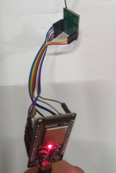
Hooking it Up The following jumpers need to be made between the ESP32 and the E22 module:
| ESP32 | E22 |
|---|---|
| GND | GND |
| VIN | VCC |
| RXEN | IO14 |
| TXEN | IO13 |
| NSS | IO18 |
| SCK | IO5 |
| MOSI | IO27 |
| MISO | IO19 |
| RST | IO23 |
| BUSY | IO32 |
| DIO1 | IO33 |

Flashing the Firmware I actually flashed the board before I even had it all hooked up. If you did not, make sure you connect an antenna to the E22 module before powering it on.
Head to the Meshtastic Flasher and select DIY V1 under the community supported boards at the bottom. The first time you flash, make sure you select the option to do an erase before flashing.
Initial Connection and Configuration Once flashed, you should now be able to unplug from the computer and power it up however you choose to do so. Give it a few seconds to boot, and you should be able to connect to it via bluetooth. If you did not add a display, use pin 123456.
IMPORTANT! - Set your max output to 22dBm in LoRA settings. This is actually full output power. Others who have built similar units have said 22dBm setting gave them a measured output of 29dBm, which is just under the 1 watt limit. I am not sure what the default setting of 30dBm would do, but my educated guess is that it just overdrives the final amplifier stage, which would likely cause distortion, possible out of band emission, and could damage the module. Update 4-15-2025: I was reading source code for Meshtastic firmware, and it appears that once it detects the E22-900M30S, DIY V1 flavor will set the maximum to 22dBm to protect the module.
From here you can configure as normal. If all is working, you should be fully functional once you set a region and let it reset!